
Morgan Utting 381 Final Project
White Box with Sliders

Fig. 1: Top view.
Overview
This is a white box about the size of a small (musical) keyboard, with two sliders across it. Inside the box is an Arduino which constantly sends serial information to a laptop via a USB cable. The laptop is running a ChucK program which parses the serial data from the box and feeds those numbers into the frequency input of two oscillators. Move the sliders, and the frequency of the oscillators will change. To the left there are low frequencies, to the right there are high ones, much like a piano (but not quantized to any musical pitch system). In the ChucK program, one oscillator modulates the microphone input as a conventional ring modulator (.op mode for Gain ugens, more on that below) and the other is an accompaniment. A Zoom H4n is used (in usb audio interface mode) as the microphone input as well as the output to the speakers. This isn’t strictly necessary but works a lot better than just the laptop’s mic and speakers, as you can change both the input and output level on the device itself (and the mics are a lot better). Headphones can be used with this project; but using speakers is a great deal better because it produces a much more interesting sound world. Both the accompaniment oscillator and the output from the ring modulator are acoustically fed (from the speakers, to the mic) back into the ringmod system, resulting in a much richer variety of sounds. This system uses a microphone input because I love to be able to sing with my machines.
Physical Systems
Parts List
Box: Five pieces of wood, one sheet of plastic, 30 screws.
Sensors: Two lengths of NiChrome wire, two small bolts, an arduino (with screws), a USB cable, two small bits of wood (the fader knobs), plenty of hot glue and solder, and about 2m of wire. Also a laptop, and optional audio interface.
Tools: Stanley knife, can’t stress this enough. Screwdriver, drill, hot glue gun, soldering iron, Arduino IDE and a copy of ChucK. A holesaw bit and a rasp were used to form the carry handle.

Fig. 2: Side/top view. Note the slightly weird (but cool) screws.
Interface Design
One of the concerns from the start of this project was that it had to be comfortable and expressive for the user. The interface was carefully designed to feel like a mixing desk or a USB midi or keyboard controller, with places to rest your palms as well as a nice comfortable finish with no burrs or sharp edges. The wooden ends were sanded to be ultra-smooth and high-quality, slightly unusual screws were selected, not only to be useful but to set it aside a little from the other pieces of gear we use to make music with. The components of any piece of gear contribute subtly to the uniqueness of that instrument, which (in the musician’s head, or at least in my head) connect with the sounds produced when playing that instrument. This is particularly important when it comes to one-off sonic arts projects or custom-made instruments, as many of these creations lack a certain identity and are often too open-ended in function to be truly considered instruments (that a user would remember fondly, and want to play again in future). Instruments need to do a small number of things, beautifully. In this way, interfaces are limited in a compositional sense, which improves them.

Fig. 3: Bottom view.
The box consists of two wooden ends, a wooden back and front, and a plastic top. It is roughly 59x22x8cm in size (length, depth and height respectively). A carry handle is cut through the back piece in order to make it more portable. All joins are made with screws. Two slits are cut in the plastic top for the sensors, with the arduino mounted on the underside of the sensor mount (another piece of wood). There is also a really subtle green power-indicator LED which shines through the plastic top in the top-right corner, just to let the user know that everything’s working. The wood was reclaimed from an old desk and some leftover 2x4, and the plastic is reclaimed 2mm shower liner. Reclaimed materials are important for several reasons: Recycling stops unneccessary wastefulness and reclaimed materials are a lot cheaper than new ones. Also, making things out of what we have rather than what we have to go and buy limits us healthily and promotes good, flexible designs.
Sensors
Not only did the interface have to be comfortable, it had to be tactile and gestural; allowing the user to make large movements accurately. The two sliders are based on conventional potentiometers, and are very simple: Each one consists of a high-resistance track (with one end connected to ground and the other connected to 5v on the Arduino) and a wiper (connected to the analog inputs of the Arduino). The track is repurposed NiChrome wire from an old fan heater, and the wiper is a filed-down bolt, turned upside down, with a wire wrapped around and soldered to it, and a wooden fader knob on top.
Two grooves were cut (~8x8mm deep/wide) into a long piece of wood. Wires were soldered onto the ends of the heater wire for ground and power. The heater wire was then hot-glued into place in the track. Corresponding slits were cut into the plastic top to allow the wiper screws to poke up through it. The piece of wood was cut to length and screwed into the box about 3mm below the plastic top, in order to let the wiper wires move properly. The edges of the wooden track and the plastic slits were trimmed and smoothed off with a stanley knife to allow the wiper to move smoothly. This part, along with just getting the plastic to sit flat, took the most time to get right in the whole project. The first plastic top was thermoformed with a heat gun around the wooden parts of the box, but it just wouldn’t sit flat enough and had to be scrapped in favour of just a flat top. The Arduino is just screwed to the underside, at a position where all the wires reach it easily. In future I might move it to the back of the box to make the USB cable faster to plug in. The sensors are surprisingly stable for such a simple redneck design; particular notes can be held and returned to very easily and musically.
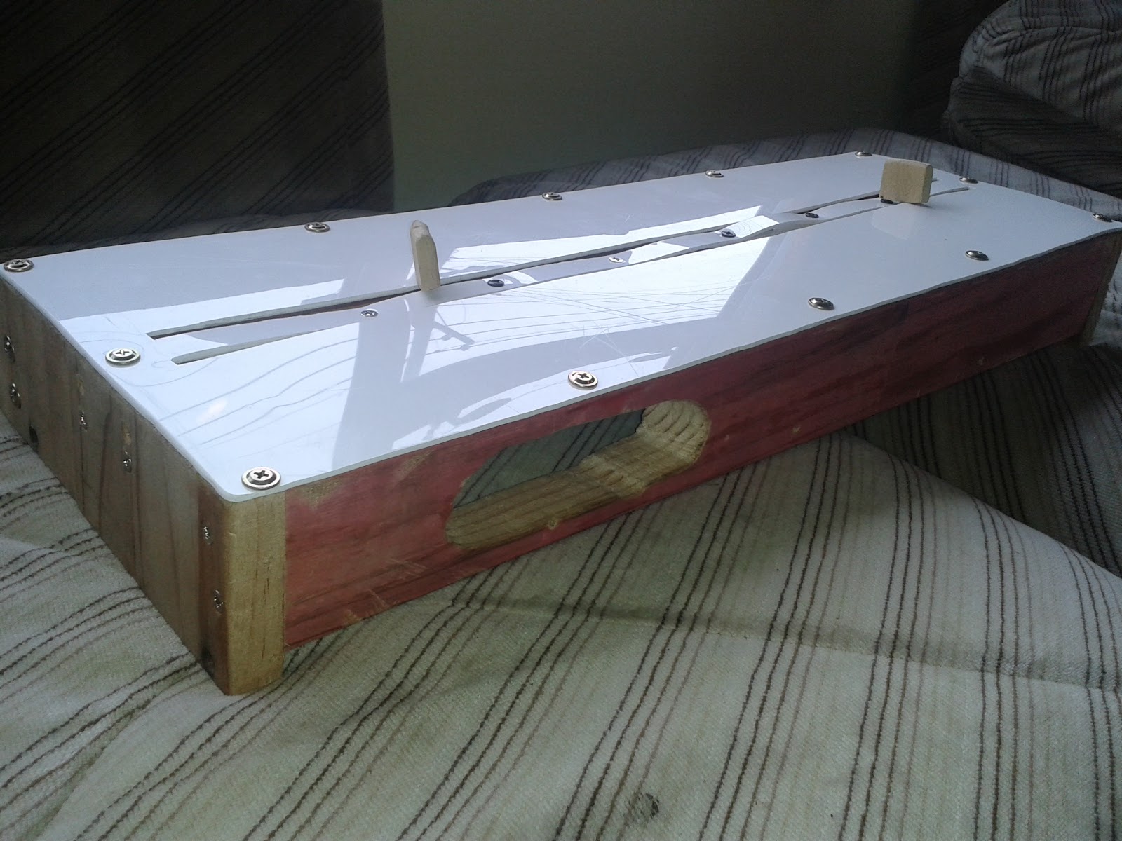
Fig. 4: Rear view. Note the carry handle. Turned out to be very useful!

Fig. 5: Close-up on the NiChrome wire tracks.

Fig. 6: Wiper with knob. A filed-down bolt has a wire wrapped around and soldered to it.
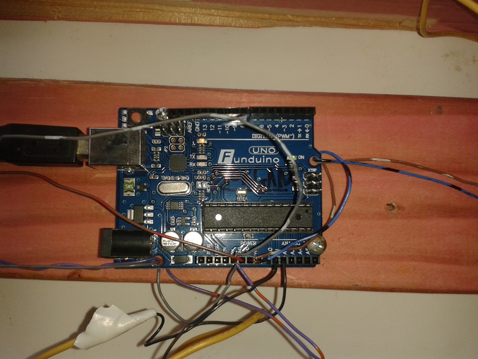
Fig.7: The Arduino Uno, with everything connected. A smaller Arduino could be used here
Firmware/Software
Arduino Code
The Arduino code is very simple (just a small paragraph). It sets up the two analog input pins (A0 and A1) and the serial, reads the pins and then prints the two values like this (minus quotation marks): “[ A0 , A1 ]” to the serial port every 10ms. By default the analogRead() system reads voltages of 0 - 5v as integers from 0 - 1023, which works really nicely here. This paragraph is actually longer than the Arduino code itself. Some signal conditioning was considered but the sensors perform so reliably that none was needed.

Fig 8: The full arduino program.
ChucK Code
Here the serial data is parsed using Regular Expressions, converted from ascii to integers, and fed into the .freq methods of the two oscillators. Regular Expressions is incredibly powerful, but also difficult to use and very easy to mess up. ChucK really needs a new, easier way to parse incoming information, particularly if they’re just comma-separated values. At the start of the code, the gain structure and the oscillators are set up, with the accompaniment oscillator going through a light delay just to give it some subtle character. The ring modulation works like this:
adc => Gain master => dac;
3 => master.op;
TriOsc s => master;
The ‘.op’ method tells the Gain ugen to multiply incoming signals instead of summing them, resulting in the sum and the difference between the signals. This was not documented anywhere and I only knew about it because of a short example I had been given last year that used it. The numbers 1 and 2, when chucked to the .op method both sound the same, and one of them probably tells the Gain ugen to operate in it’s default mode (summing).
Two shreds are sporked together in my code: The SerialPoller and the main loop. The SerialPoller is mostly unmodified code from the lecture slides which parses the serial data, converts it to integers, and then writes it to the data[] array. The main loop writes the values in the data[] array to the .freq methods of the two oscillators. The accompaniment oscillator’s frequency is halved here to give it more options for bass notes. 100ms is then passed (because of how ChucK works, you have to pass time to allow for things to happen), and the loop goes around again. I tried taking it down to 10ms (the speed the arduino is writing data to serial) but the sliders felt too sterile and there wasn’t enough rhythm happening. 100ms provides a sort of frenetic base rhythm to the performance while still being fast or responsive enough to feel accurate, and it still feels like the notes change when you move the sliders. Perhaps in future I will add a knob to the interface which controls the rate of the loop, and therefore the rhythms produced. It might be interesting to make really long rhythms that update the notes really slowly, for even more of a drone effect.
Motivation, Related and Future Works
The original motivation for this project came from an idea I had about delay units. I was messing around in Jack one day with my friend on a Raspberry Pi, and we tried out the inbuilt delay effect it had. When the delay length was shortened, the data in the latter half of the buffer remained there. This meant that when the delay time was lengthened again, the old data mixed with the new in a really interesting way. Months of daydreaming later, I had a pretty good idea of how this could be made into a physical unit; with a long slider for each of the two ends of the delay ‘window’; within a larger buffer. Unfortunately, I couldn’t figure out the exact details of how such a thing would work in ChucK, so I endeavoured to make a program that was good enough to suit the nature of the box with the sliders, which is still a great controller on it’s own. What I’ve made (with the ring modulation) is a good place to start, and it demonstrates the beauty of giant faders really well. However, I still want to write more programs to use with it; to find more ways that large, precise motions can be expressed musically.
In an earlier assignment, we had to analyse other sonic arts projects from the big NIME conferences. I chose to look at a tactile textile interface, where the user stretches and pulls on resistive thread that was sewn into a lycra sheet. While different in nature from my wooden box with sliders, the project had a similar amount of complex, large movement required from the user. This is a really interesting area of interface design that needs a lot of development. Large motions (more than controlling a small volume knob or mixer fader) which have precise effects can be incredibly expressive. A good example of this are the custom musical interfaces built by machinist and musician Tristan Shone for his one-man industrial doom metal band, Author and Punisher. In watching his performances, it’s very clear that more of his emotion can be expressed through larger motions, which gives his music a feeling of being angrier or larger or more primal. While using a lot of the same sounds and synthesiser settings, this music is the polar opposite of the typical modular analog synth musician, who daintily patches things together with little patch cables and carefully programs sequences with little buttons.
The nature of a musical interface can have a huge influence on the music that that instrument produces.
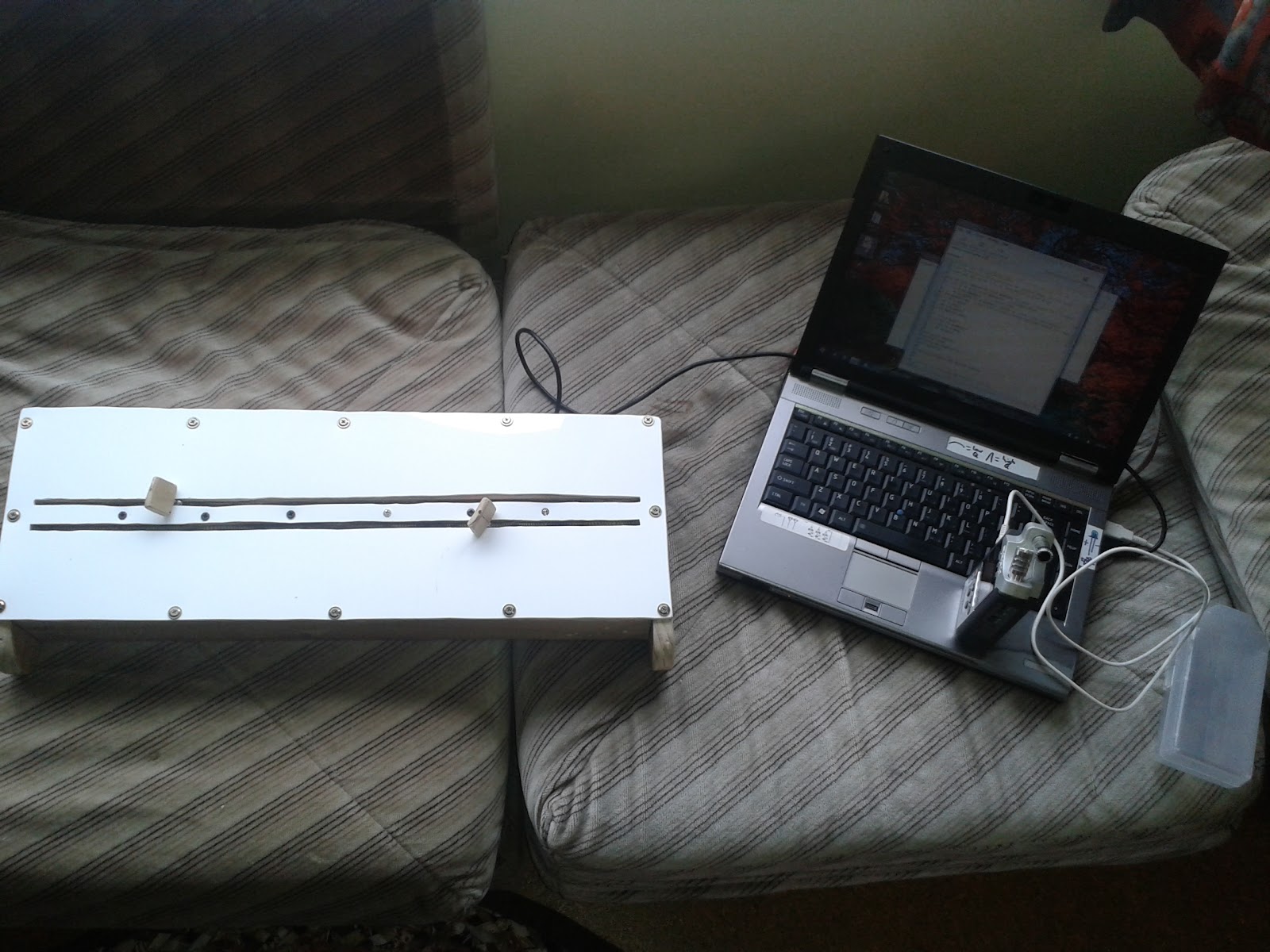
Fig. 9: The full setup, with the box, the laptop, and the Zoom mic/interface.
Finally, here's a video demo with some examples of how it all sounds: https://www.youtube.com/watch?v=BcC3-a6qjvs
Finally, here's a video demo with some examples of how it all sounds: https://www.youtube.com/watch?v=BcC3-a6qjvs
References
15min video detailing some of Tristan Shone’s work: https://www.youtube.com/watch?v=23-lRV3qNQk
NIME | Zstretch: A Stretchy Fabric Music Controller:
No comments:
Post a Comment